The half wave rectifier converts the Alternating Current (AC) into Direct Current (DC). The only solution for this is smoothing the fluctuating Direct Current (DC). This can be achieved by using a device called filter. The pulsating Direct Current (DC) contains both AC and DC components.
What is the circuit diagram of half wave rectifier?
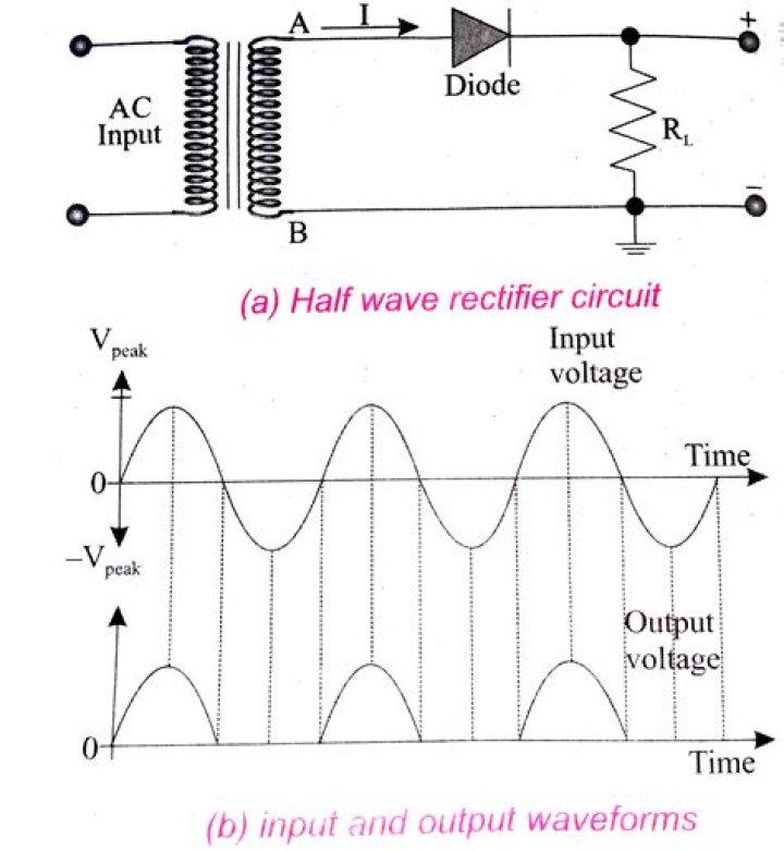
In a half-wave rectifier circuit, the load resistance is connected in series with the PN junction diode. Alternating current is the input of the half-wave rectifier. A step-down transformer takes an input voltage and the resulting output of the transformer is given to the load resistor and to the diode.
What is filter circuit in rectifier?
The filter is a device that allows passing the dc component of the load and blocks the ac component of the rectifier output. Thus the output of the filter circuit will be a steady dc voltage. The filter circuit can be constructed by the combination of components like capacitors, resistors, and inductors.
What is filter circuit and its types?
A filter circuit is a device to remove the A.C components of the rectified output, but allows the D.C components to reach the load. A filter circuit is in general a combination of inductor (L) and Capacitor (C) called LC filter circuit. A capacitor allows A.C only and inductor allows D.C only to pass.
What is rectifier with diagram?
The rectifier is an electrical system that transforms alternating current ( AC), which regularly reverses direction , to direct current (DC ) , which flows in one direction only. The technique is known as rectification, since it straightens the current direction.
What is rectifier explain the working of half wave and full-wave rectifier with diagram?
In Half Wave Rectifier, when the AC supply is applied at the input, a positive half cycle appears across the load, whereas the negative half cycle is suppressed. This can be done by using the semiconductor PN junction diode. The diode allows the current to flow only in one direction.
Why do you need a filter circuit?
The filter circuit is needed to remove the ripples from DC output voltage so that the output voltage across the load will be regulated. Filter Circuit is connected between the load and output of rectifier circuit. And in order to smooth the pulsating signal, we need a filter circuit.
What is a filter circuit?
A filter circuit is a device which removes the a.c. component of rectifier output and allows only d.c. component to reach the load. A filter circuit is generally a combination of inductors(L) and capacitors(C).
Why are filter circuits used?
To remove the AC components or filter them out in a rectifier circuit, a filter circuit is used. A filter circuit is a device to remove the A.C components of the rectified output, but allows the D.C components to reach the load. For example, an inductor allows the D.C to pass through it.
