The inductance of a conductor is given by the ratio of total magnetic flux linkages to the current flowing through it. The total magnetic flux linkage is flux linkage to a conductor due to its own current and due to current in the neighboring conductors.
What are the parameters of transmission line?
The transmission line has mainly four parameters, resistance, inductance, capacitance and shunt conductance. These parameters are uniformly distributed along the line.
What is the inductance of 1 phase transmission line?
The changing flux links the loop and hence the loop (or single phase line) possesses inductance. It may appear that inductance of a single phase line is negligible because it consists of a loop of one turn and the flux path is through air of high reluctance.
How is transmission line capacity calculated?
Power Transmited
- At 132 kv. Power in MW = Ö 3 132 x I x 0.8 / 1000. = 0.1828992 x I. = 0.183 x I.
- At 220 kv. Power in MW = Ö 3 220 x I x 0.8 / 1000. = 0.305 x I.
- At 400 kv. Power in MW = Ö 3 400 x I x 0.8 / 1000. = 0.554 x I.
What is the formula for transmission line efficiency?
Efficiency of Transmission Line Transmission efficiency is defined as the ration of receiving end power PR to the sending end power PS and it is expressed in percentage value. cosθs is the sending end power factor. cosθR is the receiving end power factor. Vs is the sending end voltage per phase.
How do you calculate transmission line efficiency?
Efficiency of Transmission Line Transmission efficiency is defined as the ration of receiving end power PR to the sending end power PS and it is expressed in percentage value. cosθs is the sending end power factor. cosθR is the receiving end power factor.
What are the factors depend on the inductance of transmission line?
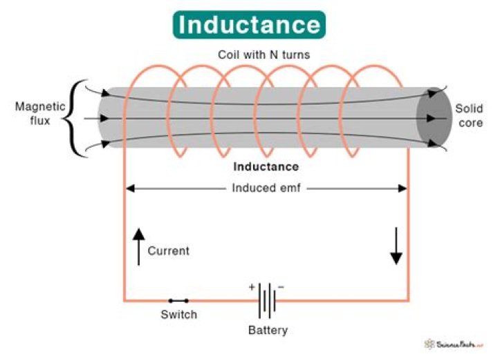
Following factors affect the inductance in a circuit:
- Number of Wire Turns in the Coil. The greater the number of turns of wire in the coil, the greater the inductance.
- Coil Area. The greater the coil area, the greater the inductance.
- Core Material.
- Coil Length.
How inductance is formed in transmission lines?
The internal flux is induced due to the current flow in the conductor. The external flux produced around the conductor is due to its own current and the current of the other conductors place around it. The total inductance of the conductor is determined by the calculation of the internal and external flux.
What is transmission line equation?
The wave velocity, v = ω/γ, is the speed with which a peak in the wave propagates along the transmission line. The wavelength, λ = 2π/γ, is the distance between peaks in the wave at a particular point in time.
How do you find the inductance of a line?
Calculation of Inductance of Single Conductor And magnetic flux density Bx = μHx, where μ is the permeability of this conductor. Again, µ = µ0µr. If it is considered that the relative permeability of this conductor µr = 1, then µ = µ0.
What is the inductance of transmission line?
Inductance of Transmission Line In the medium and long transmission lines inductance (reactance) is more effective than resistance. The current flow in the transmission line interacts with the other parameter, i.e the Inductance. We know that when current flow within a conductor, magnetic flux is set up.
What are the parameters of transmission lines?
The transmission lines are the electrical circuits having parameters or constants like resistance, inductance, capacitance and shunt conductance, which are distributed along the entire length of the line as shown below. Resistance and inductance are the series parameters whereas capacitance and shunt conductance are the shunt parameters.
What is the formula for inductance of a phase line?
Observing the formula for single phase and three phase lines we can generalize the formula for inductance of a phase line as in the form L = 2 * 10-7 ln (D / Ds)
How to calculate the total inductance of a conductor?
The total inductance of the conductor is determined by the calculation of the internal and external flux. Considered a single phase line consisting of two conductors (phase and neutral) a and b of equal radius r. They are situated at a distance D meters. The cross sections of conductors are shown in the diagram below.
